Once a chemical contaminant breaches the land surface, enters the unsaturated vadose zone, and dissolves into a groundwater aquifer, an environmental catastrophe begins in near-total darkness. Because groundwater moves slowly and lacks sunlight and atmospheric exposure, natural dilution and biological breakdown are severely attenuated. A single 55-gallon drum of chlorinated industrial solvent leaked into an alluvial aquifer can contaminate over one billion gallons of pristine drinking water above statutory maximum contaminant levels (MCLs), generating a subterranean contamination plume that persists for generations.
Managing and remediating subsurface contamination requires mastering the physical transport mechanisms of Advection, Mechanical Dispersion, Molecular Diffusion, and Retardation ($R_d$). In this monograph, we examine the behavior of Light vs. Dense Non-Aqueous Phase Liquids (LNAPLs vs. DNAPLs), landfill leachate migration, and modern remediation engineering—from pump-and-treat systems to Permeable Reactive Barriers (PRBs) and in-situ enhanced bioremediation.
The Four Fundamental Solute Transport Mechanisms in Porous Media
When dissolved chemical molecules migrate through an aquifer, their spatial spread is governed by the Advection-Dispersion Equation (ADE):
- Advection: The transport of dissolved solutes by the bulk motion of flowing groundwater, moving at the mean linear seepage velocity: $v_s = (K \cdot i) / n_e$.
- Mechanical Dispersion: The spreading of the plume caused by localized velocity variations at the microscopic pore scale (friction along pore walls, tortuous winding flow paths, and variable pore throat widths). Quantified via the longitudinal dispersivity coefficient: $D_L = \alpha_L \cdot v_s$.
- Molecular Diffusion: Spontaneous spreading driven by chemical concentration gradients ($dC/dx$) according to Fick’s Second Law. While negligible in fast-moving sands, diffusion dominates solute transport inside tight clay aquitards and rock matrices.
- Adsorption and Retardation ($R_d$): Hydrophobic organic chemicals adsorb onto solid organic carbon coats on mineral grains, slowing their forward advance relative to pure water flow:
Rd = 1 + (ρb / n) * Kd
Where $\rho_b$ is soil bulk density, $n$ is total porosity, and $K_d$ is the distribution coefficient ($K_d = f_{oc} \cdot K_{oc}$). A retardation factor of $R_d = 4$ means the toxic chemical plume travels at only one-fourth the velocity of the surrounding groundwater!
| Contaminant Class | Physical State & Phase | Density Relative to Water (ρ) | Primary Sources & Compounds | Subterranean Fate & Behavior |
|---|---|---|---|---|
| LNAPL (Light Non-Aqueous Phase Liquid) | Immiscible Liquid | Lighter than water (ρ < 1.0 g/cm³) | Gasoline, diesel, crude oil, benzene, toluene (BTEX) | Pancakes along the capillary fringe on top of the water table; forms floating lens |
| DNAPL (Dense Non-Aqueous Phase Liquid) | Immiscible Liquid | Heavier than water (ρ > 1.0 g/cm³) | TCE (Trichloroethylene), PCE (Tetrachloroethene), creosote | Drives straight down through the water table to the impermeable bedrock floor! |
| Inorganic Anionic Plumes | Aqueous Dissolved Ions | Dissolved in water | Agricultural nitrate (NO3-), road deicing salt (NaCl) | Conservative non-retarded advective transport; massive regional plumes |
| Landfill Leachate | Complex Aqueous Cocktail | Variable | Municipal MSW landfills: ammonia, heavy metals, VOCs | High BOD/COD, reducing plume, black anaerobic core |
| PFAS (‘Forever Chemicals’) | Perfluoroalkyl Substances | Surfactant / Aqueous | AFFF fire fighting foam, Teflon manufacturing, PFOA/PFOS | Extremely resistant to biological and chemical breakdown; long plumes |
Landfill Leachate Plume Geochemistry and Redox Zonation
When rainwater percolates through unlined municipal solid waste (MSW) landfills, it dissolves organic decomposition products, yielding concentrated landfill leachate (characterized by $BOD > 10,000 \text{ mg/L}$, ammonia, and volatile organics). As this leachate plume moves down-gradient, it alters the natural aquifer into a concentric series of reverse redox zones: an intensely reducing methanogenic and sulfate-reducing core near the landfill, surrounded by an iron-reducing zone (where native iron minerals dissolve, releasing dissolved iron into the water), grading outward through a manganese-reducing fringe into natural aerobic groundwater.
Remediation Engineering: Pump-and-Treat vs. Permeable Reactive Barriers
Traditional environmental engineering relied on Pump-and-Treat: pumping contaminated water out through extraction wells and treating it at the surface. However, because contaminants slowly desorb from clay pores (tailing and rebound), pump-and-treat can take over 100 years to clean an aquifer! Modern remediation utilizes passive, in-situ technologies:
- Zero-Valent Iron Permeable Reactive Barriers (ZVI-PRBs): A subterranean trench excavated directly across the path of a moving DNAPL plume and backfilled with granular zero-valent iron scrap ($Fe^0$). As contaminated groundwater flows naturally through the iron wall, abiotic reductive dechlorination ($Fe^0 + \text{R-Cl} + H^+ \rightarrow Fe^{2+} + \text{R-H} + Cl^-$) strips chlorine atoms from TCE and PCE, converting toxic solvents into harmless ethylene and chloride ions without pumping a single drop of water to the surface!
- Enhanced Reductive Dechlorination (ERD Bioremediation): Injecting food-grade electron donors (such as emulsified vegetable oil or lactate) into the aquifer to stimulate specialized anaerobic bacteria (specifically Dehalococcoides mccartyi), which enzymatically breathe chlorinated ethenes, converting them completely to non-toxic ethene gas.
Dense Non-Aqueous Phase Liquid (DNAPL) Multiphase Flow Mechanics
When an immiscible liquid (such as chlorinated degreaser trichloroethylene, TCE) migrates through an aquifer, its movement is governed by Capillary Pressure ($P_c$) and two-phase relative permeability relationships:
Pc = Pnw – Pw = (2 * γ * cosθ) / r
Where $P_{nw}$ is non-wetting fluid pressure, $P_w$ is wetting fluid pressure, $\gamma$ is interfacial tension between TCE and water, $ heta$ is contact angle, and $r$ is the pore throat radius. To invade a fine-grained water-saturated sediment layer (such as a silty sand or clay lens), the DNAPL must exceed the Capillary Entry Pressure ($P_{entry}$). If the pooled height of DNAPL is insufficient to overcome entry pressure, the solvent spreads laterally along the top of the clay lens, forming complex horizontal pools that make drilling extraction nearly impossible.
PFAS Contamination: The Fluorinated Surfactant Interface Challenge
Per- and polyfluoroalkyl substances (PFAS) present unique hydrogeological transport challenges. Featuring a fully fluorinated hydrophobic carbon tail bonded to a hydrophilic anionic head (such as perfluorooctane sulfonate, PFOS), PFAS molecules behave as surfactants. In unsaturated vadose zones, PFAS molecules preferentially accumulate at the air-water interface, where interfacial adsorption retards plume migration by orders of magnitude compared to traditional organic solutes, creating vast invisible reservoirs that leach into underlying drinking water aquifers for decades.
Thermal In-Situ Remediation: Electrical Resistance Heating (ERH)
When dense non-aqueous phase liquids (DNAPLs) pool in tight, low-permeability silt and clay layers deep below the water table, standard pumping and chemical flushing fail because fluids cannot circulate through tight pores. In such severe scenarios, environmental remediation engineers deploy Thermal In-Situ Remediation, specifically Electrical Resistance Heating (ERH):
Arrays of massive steel electrode rods are drilled into the contaminated clay formation, and three-phase AC electrical power is applied directly across the subterranean zone. Electrical resistance through the moist clay heats the entire soil matrix and groundwater to the boiling point of water ($100^\circ\text{C}$). As groundwater boils into steam, it co-boils and co-volatilizes the trapped chlorinated solvents (which boil at lower azeotropic temperatures, e.g., $73^\circ\text{C}$ for TCE-water azeotropes). The contaminated steam is captured by vacuum extraction wells, pulled to the surface, and condensed for destruction via thermal oxidizers, achieving over 99.9% DNAPL mass removal from impervious clay within months.
Monitored Natural Attenuation (MNA) Protocol Benchmarks
Under US EPA guidelines, Monitored Natural Attenuation (MNA) relies on natural subterranean physical and biological processes to clean a plume without active mechanical pumping. To gain regulatory approval for MNA, hydrogeologists must provide three ‘lines of evidence’: first, historical groundwater monitoring demonstrating a shrinking or stable contaminant footprint; second, geochemical telemetry confirming active biodegradation (depletion of electron acceptors $O_2$, $NO_3^-$, $SO_4^{2-}$, and production of metabolic byproducts $Fe^{2+}$, $CH_4$, and chloride ions); third, microbiological molecular confirmation (such as quantitative PCR detecting functional reductive dehalogenase genes tceA, bvcA, and vcrA in resident bacteria).
Monitoring Well Drilling, Development, and Hydrogeological Sampling
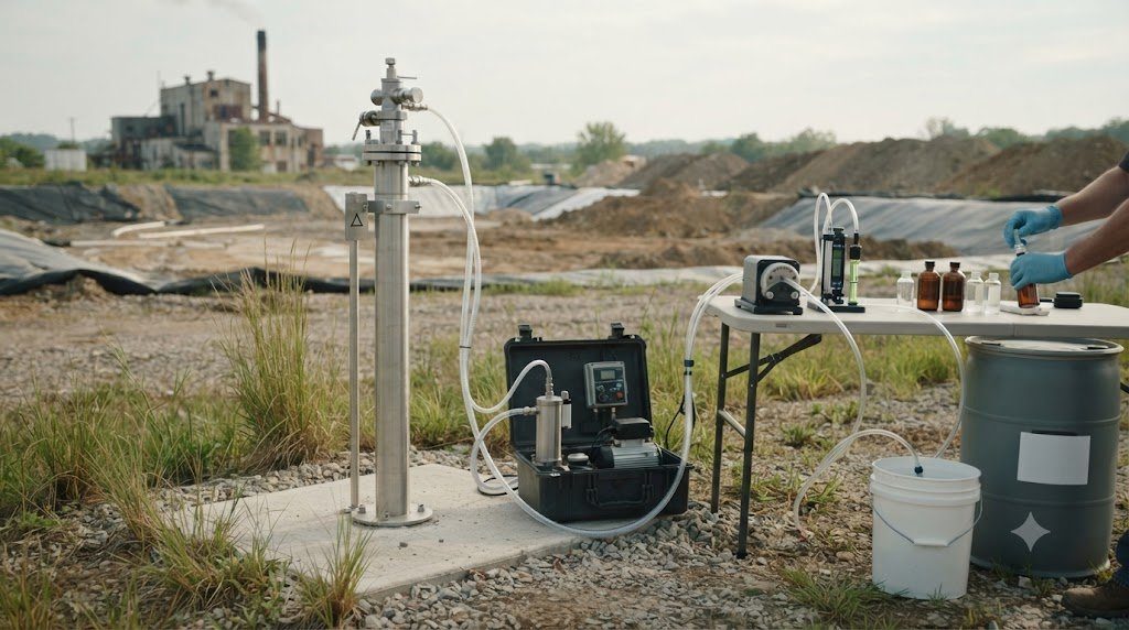
Validating the hydrogeological principles of Groundwater Contamination Hydrogeology requires installing, developing, and sampling certified groundwater monitoring wells. If a monitoring well is drilled with inappropriate muds or sampled using high-flow pumps that aerate the water, dissolved volatile organic compounds (VOCs) strip out and dissolved metals precipitate onto casing walls, generating invalid laboratory data.
A professional hydrogeological investigation follows strict EPA and USGS low-flow purge protocols to ensure that water extracted from the borehole represents true, undisturbed aquifer conditions. Use the well development and sampling matrix below.
| Hydrogeological Stage | Drilling Rig / Sampling Hardware | Operational Objective | Standard Field Procedure | Critical Contamination Safeguard |
|---|---|---|---|---|
| Borehole Drilling | Hollow-Stem Auger or Sonic Rig | Penetrate target saturated aquifer zone | Log lithological soil cores every 5 feet; record depth to water table | Never use bentonite drilling muds in screen zone; use clean water only |
| Well Installation | 2-inch Schedule 40 PVC; 0.010″ slotted screen | Establish permanent intake zone | Pack screen with graded 20/40 silica sand; seal above with 2ft bentonite pellet plug | Cap wellhead with locking steel protective casing bolted into concrete pad |
| Well Development | Surge block & high-capacity submersible pump | Remove drill fines & develop gravel pack | Surge and pump until turbidity drops below 10 NTU; flush at least 5 casing volumes | Prevents silting of pump impellers and ensures natural hydraulic conductivity |
| Low-Flow Purging (Low-Flow Micro-Purge) | Adjustable-rate bladder pump or peristaltic pump | Extract formation water with minimal drawdown | Pump at 100 to 500 mL/min; log pH, DO, ORP, Temp, Specific Conductance in flow cell | Purge until 3 consecutive readings over 5-minute intervals stabilize within 10% |
| Sample Collection | Direct filling of laboratory certified glass VOA vials | Capture VOCs, heavy metals, and nutrients | Fill 40 mL VOA vials to positive meniscus without headspace/bubbles; preserve with HCl | Zero air bubbles in vials; keep samples chilled at 4°C in dark cooler |
Flow-Through Cell Parameter Stabilization Criteria
During low-flow micro-purging, groundwater is pumped through an enclosed, sealed multichannel flow-through cell containing calibrated probes. Pumping continues until parameters achieve strict stabilization over three consecutive readings spaced 3 to 5 minutes apart:
- pH: Stable within $\pm 0.1 \text{ pH units}$.
- Specific Electrical Conductance: Stable within $\pm 3\%$ of reading.
- Dissolved Oxygen (DO): Stable within $\pm 10\%$ (or $\pm 0.2 \text{ mg/L}$ when $< 2.0 \text{ mg/L}$).
- Oxidation-Reduction Potential (ORP): Stable within $\pm 10 \text{ millivolts}$.
- Turbidity: Stable within $\pm 10\%$ (and ideally $< 10 \text{ NTU}$).
Frequently Asked Questions Concerning Hydrogeology & Aquifers
What is the difference between porosity and permeability?
Porosity ($\eta$) is the percentage of total rock or sediment volume occupied by open void spaces, representing how much water an earth material can hold. Permeability ($k$) is the measure of how easily fluids can flow through those voids, depending on pore size and interconnectivity. A dense clay can have high porosity (45% voids) but near-zero permeability because its microscopic pore throats are too narrow for water to move freely.
How does a cone of depression cause land subsidence?
When an extraction well pumps groundwater faster than the aquifer recharges, hydraulic head drops in a conical depression around the well. Relieved of pore water pressure ($u$), the overburden weight of overlying rock and buildings transfers directly onto the mineral skeleton, compressing compressible clay layers and causing irreversible ground collapse and surface subsidence.
Why are karst aquifers particularly vulnerable to pollution?
Standard sand aquifers filter water through microscopic pores, removing bacteria and suspended particles via physical filtration and slow biological breakdown over years. In karst limestone aquifers, water rushes through open dissolved caves and conduits at kilometers per day with zero filtration. A chemical or septic spill at a surface sinkhole travels unfiltered straight to municipal drinking water taps within hours.